Crop Circles in 3D …

Haiku

Jedi Master
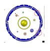
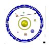
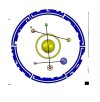
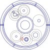
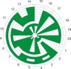
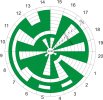
I am looking at modeling crop circles in a 3D modeling software, SolidWorks. I am getting crop pictures from this site, http://temporarytemples.co.uk/crop-circles/2015-crop-circles . Using an image importing into my modeling program, enlarged so that the tracks in the field are to my 150” dimension (see assumptions below). My first problem is that the images are not going to be straight up perpendicular to the field, they are skewed a little. I will be fudging the data a little, just for you to know. Once I model this in 3D, I plan on animating it so it will orbit like planets in a solar system or electrons in a molecule. This first one was interesting to me so I started there. It is the one at Maiden Castle in 2015. I chose this one as I was wanting one with external information to support defining it. The ring around the center is loaded with information, similar symbols in varied locations, and more to figure out. I will start here and model the basic structure and simulate it. I am in no way an expert in crop circles, I can model them. I do have my own thoughts about them which I will present …

If there is a someone or a group working on this, please I would be very interested in assisting in any way possible. If not, then I am looking for others that can assist in deciphering and selecting projects. I figure that I am not the first person to investigate this, so I hope that there will be plenty of minds here with similar thoughts.

My assumptions are;
1. This field is rather large to begin with and I suspect that a combine, or similar equipment, was in use here. Standard combine dimensions vary and after a little research I found them to be roughly 150” (3.75M) ± 10”. If there is any other information on this, I am interested to hear it or actual dimensions from each field. I have modeled the crop circle to size. All helps …
2. I am using the widest points in the image as the diameter of the objects. My want of simpler spherical items for this first one is why I selected it.
3. Once I get the largest diameter defined, I am going to tweak the image by stretching it and forcing it round … er.
4. The animation is going to be a constant speed directly of the modeled objects. I suspect that there is information loaded in the outer ring. I figure that it is extremely important to the correct simulation/display of this crop circle and/or understanding of the presented data.

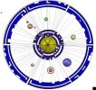
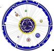
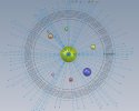
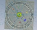
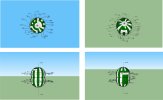
Alright I have finished a rough version of my first project. It took some time and I want to keep going on it, but I am stopping here. I have crude and quick animations that I have attached. It seems to me that this is a static image, not a moving image. Open the PDF first, it gives general information. I have it showing in 3 versions, I am not sure which one to present, so you get all ways. The image is the one I built this field from. The planetary positions for the day of the event, also shown (I added this but do not want those to only see it as this). I also added a markup of the PDF of what I think about this crop circle, please do not open until you think about what is being presented. The colors were applied with no intent of identification.

Why am I doing this now? I have been doing my homework and re-reading everything, this is something that I came across from varied sessions and is something that I can assist with. I will need help and guidance. Haiku …
 

Attachments

  • maiden castle 2015_1_Haiku.pdf
    1.2 MB · Views: 46
  • maiden castle 2015_1.pdf
    295.7 KB · Views: 24
  • maiden castle 2015_1_Haiku.pdf
    1.2 MB · Views: 33
  • maiden castle 2015_1.pdf
    295.7 KB · Views: 96
I have completed 2 more. One is Matterley Basin and the other is Hackpen Hill, both from 2016. Neither ended up what I thought they would be. Both are geometric structures, granted I have taken some liberties for symmetry needs. I am attaching some 3D PDF files that allow rotation and viewing of the models.

Hackpen Hill

This is a composite angle nightmare. It is all based on 15/30/45° angles. The first model was a flat platter structure. Then I looked at the perimeter circle and thought about what this would be in 3D, as a sphere. I modeled the exterior shell so it is transparent. This inner structure when looked at from the top looks like the crop circle. Then as you rotate it around the shape takes on a completely different view. The 3D file on this one shows the model well. I may be wrong on this being spherical.

Matterley Basin

This one made the last one look like a cake walk, it had many composite angles in the flat faced body that took some time to understand. The 3D on this one has a little difficulty displaying faces as you will see. I may be completely wrong in certain areas of this one due to what I see in the object.
I do have SolidWorks 2012 models on these if you are interested I can give you copies of them in native or other translated formats. These were fun, well fun for someone like me. I am glad to be able to let you see them in the 3D files so you can really see them. Haiku …
 

Attachments

  • hackpen hill 2016.pdf
    226.8 KB · Views: 37
  • Matterley Basin 2016.pdf
    175 KB · Views: 26
  • hackpen hill 2016_3D.pdf
    1.1 MB · Views: 22
  • Matterley Basin 2016_3D.pdf
    569.2 KB · Views: 22
This one might be too big but here is maiden castle. Haiku ...
 

Attachments

  • maiden castle 2015_3D.pdf
    1.5 MB · Views: 45
Hello Haiku. Thank you for this thread. I find it really interesting.

Maiden castle circle clicks me in some way. Even though it's strange.

When I try to derive some conclusions from what I see in a picture the concept slips away or looses its charm:) Maybe the key to "read" it is in this uncertainty?
For example together with a dot you've mentioned before there's another symbol kind of isolated in the rim. It looks like minus or dash. (See picture attached). Dot symbol is close to the size of the smallest object inside the circle. Could it be direction to "read"? Well... here's where the option start to pile up.
1) Are dash and dot the letter of Morse code? Short and long sound signal. Short and long wave frequency?
2) It is normal for us to put a period in the end of every sentence. So maybe the dot on the rim is the End and dash seen as a line of dots is the Beginning (continuity, prolongation)? It is normal and habitual for us to have a dot as the end but was it all the time. Is it so in every language? Was the concept of the dot the same before the invention of writing and later punctuation?
3) If you put a dot on a blank sheet of paper, draw it on a ground or sand it looks like beginning. Something not yet certain is about to emerge. On the other hand dash seen as minus obliterates dot. Something abstract and potent became concrete and defied. So dash could be the End too.
 

Attachments

  • 1_dotnnot.jpg
    1_dotnnot.jpg
    169.8 KB · Views: 279
  • 3_the_small.jpg
    3_the_small.jpg
    164.4 KB · Views: 273
Speaking about the "planets". Are they really planets?
I may assume these are rather symbolic that exact representations of the planets. These circles are set on the same "orbit" around the central object. They are united or maybe unified:) The central object could be the Sun. If I follow this line of thinking I have to admit that object accompanied by two smaller circles most likely is Mars. The largest object "spinning" around the central Object is Jupiter. Next to "Jupiter" is circle with a rim, so it could be Saturn?
Alright, if that's really so than we have to keep in mind that in a picture there is another object with a rim - the most largest ant central one. So if central circle is the Sun it must have rings:) Or if rim is actually a representation of something emanating, our Saturn must be shining as the Sun do:)

Our "Mars" and yellowish object are approximately of the same size. Smaller object with a rim - our "Saturn" - is approximately of the same size as green circle across. Two small objects clearly(?:)) belong to our "Mars" and should be seen together. We are left with the largest and the smallest circles alone.

My speculation is:
1) Our "Mars" is fraction, fragmentation, diversity, heterogeneity. Our yellow thing is opposite to fraction so... unity, solidity, equality, homogeneity.
2) Our "Saturn" which I assume is something that has a field, aura... Is moving, spreading, glowing, inflating, emanating. The green circle accordingly represents stop, stagnation (or reduction), dullness, deflection, moving inwards.
3) Our "Jupiter" together with pink thingy are major and minor, center and periphery, important and insignificant, primal and secondary etc...
 
If we imagine a straight line connecting these pairs we get:
1) The axis of our "Saturn" with green circle splits our "Sun" in two halves
2) The axis of yellow circle and "Mars" touches the glow of our "Sun"
3) "Jupiter" with its pink companion do not interfere with the "Sun"
 

Attachments

  • 5_pair_axis.jpg
    5_pair_axis.jpg
    169 KB · Views: 260
Thank you Zee Ley for your responses. Maiden castle looked like it had decipherable elements in it, this is why I started with this one. The dash and dot, I did not even notice the dash by the way, are interesting. Your deductions are directed and thoughtful. It is good to see someone else that see this as some kind of planetary display and then something totally different, this is where I am. The dash, now that I look at it, may also be in other portions of the ring as it may get a short notch coincidently near them. But with all of them making the L shape this may be highly unlikely but not impossible. The object definitely makes you think in opposite directions, often, I see that myself. The line theory is something I never saw. I want to plot these and see if I get any close or definable angles here. The other objects that I just posted this week had seriously defined angular points that you had to follow to make the crop circle. This one may have ones that I am not seeing… yet. Haiku …
 
I want to plot these and see if I get any close or definable angles here. The other objects that I just posted this week had seriously defined angular points that you had to follow to make the crop circle. This one may have ones that I am not seeing… yet.

Haiku, could it be stereo-graphic projection of something? if it makes sense what I've just said.
This video [_https://www.youtube.com/watch?v=yJZP_-40KVw] is about geometry of map making. From approximately 7th minute it gets to the point of how to make this projection.
I'm not good in mathematics so here I can only guess that if this method can be applied to maiden castle crop circle the blue edge with symbols and "the Sun" in a middle of the disc could be "the North" and accordingly "the South" poles of the Globe in 3D model. And objects inside the disc may change their seizes.
 
I don't really know exactly what I have done:) That is how I understood concept of projection from the video. So here are two versions of reverse projection of the blue edge symbols.
Second one is actually complete projection.
The first time I was curious to see what will happen if I stop at the edge of "the Sun"

"Planets" seem to be on the equator of the sphere.
 

Attachments

  • mid_sun_pro.jpg
    mid_sun_pro.jpg
    206.3 KB · Views: 186
  • true_pole_pro.jpg
    true_pole_pro.jpg
    206.9 KB · Views: 184
Today’s object is the Stonehenge crop circle that is recorded on 7 July 2016.

33 meters (108 ft.) diameter circle of standing stones in the outer ring at Stonehenge. My object is 430 ft. in diameter. It is located one object diameter from the field edge. It looks to be located directly south of center of Stonehenge. It is not pointing directly north at Stonehenge. My object still needs some work but I am close enough to present. On the PDF I have a few of the images that I started with and a few others I found to help. There is a 3D PDF available of just the object.

Just to note that I am just getting back to Maiden Castle as I was busy with the Stonehenge project. I have not reviewed the video yet. I did not want to look at this item with any other influences. Then I will look at your video and again at your information and see if there are any consistencies. Then I will present what I found. Haiku …
 

Attachments

  • stonehenge2016_3D.pdf
    602.2 KB · Views: 18
  • STONEHENGE1.pdf
    500.8 KB · Views: 16
Zee Ley, Here are a couple of images of sketch lines that I used to create Maiden Castle. It is good to see another that is seeing all of the lines that i saw when i built this item. Conveyance of similar thinking patterns are found everywhere. Haiku ...
 

Attachments

  • stonehenge 2016_12.JPG
    stonehenge 2016_12.JPG
    140.4 KB · Views: 15
  • stonehenge 2016_13.JPG
    stonehenge 2016_13.JPG
    154.5 KB · Views: 13
Zee Ley, Here are a couple of images of sketch lines that I used to create Maiden Castle. It is good to see another that is seeing all of the lines that i saw when i built this item. Conveyance of similar thinking patterns are found everywhere. Haiku ...

Thank you Haiku.
One idea struck me while doing this projection thing. We, I mean all people, are these patterns. Crop circles somehow open us up when we are keen to align with them. Speculation? Maybe... But to me it makes sense.
 
Zee Ley, took a quick look at the angles in the crop circle. I am sure that the deviations from 5° increments is just from the image skew that I started with. I am sure that this extends into the outer ring also and the notches that I put in it. Anyway here is the latest on Maiden Castle. Haiku ...
 

Attachments

  • maiden castle 2015 - Sheet2.pdf
    24.7 KB · Views: 13
Haiku, another strange direction that I've noticed. What if this object is meant to be in motion?

Here are some relations between planetary bodies, which suggests some sort of mechanical dynamics involved. I'm not sure if circles outlined in red should touch each or it is just a consequence of deviation.

I found out there is such a term as Epicyclic or planetary gearing:

_https://en.wikipedia.org/wiki/Epicyclic_gearing said:
...a gear system consisting of one or more outer gears, or planet gears, revolving about a central, or sun gear. Typically, the planet gears are mounted on a movable arm or carrier, which itself may rotate relative to the sun gear. Epicyclic gearing systems also incorporate the use of an outer ring gear or annulus, which meshes with the planet gears. Planetary gears (or epicyclic gears) are typically classified as simple or compound planetary gears.
So we have planets, we have sun gear and outer ring gear. The smallest object orbiting our Mars could be the starting point from where "machine" should start its motion. That's why I think it has a twin in a blue edge area (that dot symbol)

Some history:
the same source said:
In the 2nd-century AD treatise Almagest, Ptolemy used rotating deferent and epicycles that form epicyclic gear trains to predict the motions of the planets. Accurate predictions of the movement of the Sun, Moon and the five planets, Mercury, Venus, Mars, Jupiter and Saturn, across the sky assumed that each followed a trajectory traced by a point on the planet gear of an epicyclic gear train. This curve is called an epitrochoid.

Epicyclic gearing was used in the Antikythera Mechanism, circa 80 BCE, to adjust the displayed position of the moon for its ellipticity, and even for the precession of the ellipticity. Two facing gears were rotated around slightly different centers, and one drove the other not with meshed teeth but with a pin inserted into a slot on the second. As the slot drove the second gear, the radius of driving would change, thus invoking a speeding up and slowing down of the driven gear in each revolution.

Richard of Wallingford, an English abbot of St Albans monastery is credited for reinventing epicyclic gearing for an astronomical clock in the 14th century.[4]
 

Attachments

  • maid_castle_epy.jpg
    maid_castle_epy.jpg
    240.6 KB · Views: 6
My two cents:)

2010 July 21 crop circle(1)

I tried the same trick with projection. Didn't work this time... If we take instead of a sphere two dome shape objects and combine them in a certain way(2) there is a chance to make 3D shape(3).

Each dome has its own pole, 5(+1) horizontal and 20 vertical sections. +1 means the last horizontal section of both domes. It is identical. I tried number of different ways to combine domes. This is the way I end up with(4). And it seems that combined objects should move. "It's alive!" as once said mad professor:) I am sure about that because overlap area is not defined. This creates a situation where it's difficult to decide which dome should overlap where. Both domes are on the same axis. By spinning them along this axis but in opposite directions we will eventually cover entire overlap area.
Unfortunately I have neither skills nor knowledge to show it on a graphic or video.
 

Attachments

  • wiltshire_2010.jpg
    wiltshire_2010.jpg
    420.2 KB · Views: 4
  • wiltshire_2010_var.jpg
    wiltshire_2010_var.jpg
    437.1 KB · Views: 7
  • wilsh_sides.jpg
    wilsh_sides.jpg
    286.4 KB · Views: 16
  • wilsh overlap.jpg
    wilsh overlap.jpg
    28.9 KB · Views: 14
Back
Top Bottom